
Electronics Fundamentals:Passive Components
As earlier we know the passive components are couldn't be the source of power. or they can't introduce the net energy into the circuit.
As earlier we know the passive components are couldn't be the source of power. or they can't introduce the net energy into the circuit.
SOME EXAMPLES OF PASSIVE COMPONENTS:
RESISTORS:
Resistance is a measure of component's opposition to the flow of current. It is measured in ohms. The voltage across a resistance and the resulting current flowing through it are interrelated to the resistivity of the material and the length of the conductor and inversely proportional to the area of cross section of the conductor.
 |
| resistors |
V=IR
R=የ(l/A)
l-length of conductor
A-area of cross section
የ - resistivity of material
P=VI
P=I^2 R
P=V^2/R
V-VOLTAGE
I-CURRENT
P-POWER
R-RESISTANCE
SPECIFICATIONS OF RESISTORS:
Resistance value , tolerance and wattage rating are the major performance specifications of resistors. Tolerance is the permissible +/- resistance variation in the nominal resistance value.WATTAGE or power rating is the maximum power that a resistor safely can dissipate at the specified ambient temperature.
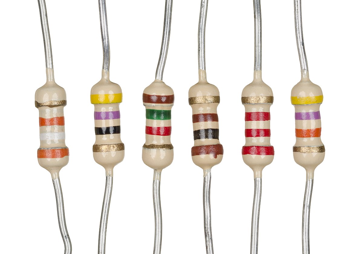
Colour coding of a Resistor:
colour coding is the standard process for marking a standard resistance value. we are using a 4-band colour code. Let's see what they represent,
three bands in the extreme left represents the resistance value, first band represents significant digit of first value and second band represents significant digit of second value and the third band represents decimal multiplier.The right side colour band represents tolerance value.
the representations as follow,
0-black
1-brown
2-red
3-orange
4-yellow
5-green
6-blue
7-violet
8-grey
9-white
these colours also respectively represents multipliers 10^0 to 10^9. +/-5% and +/-10% tolerance are respectively represented by golden and silver colour.
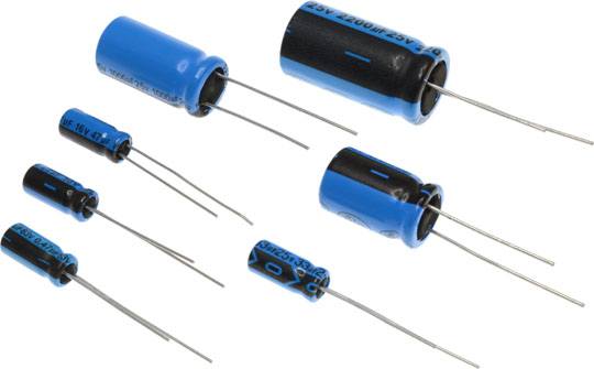
CAPACITORS:
In the most basic form, a capacitor is constituted by two parallel conducting plates separated by an insulating medium. An ideal capacitor does not dissipate any power.
 |
| capacitors |
V=1/C ∫I dt
I= C dv/dt
v-voltage
i-current
c-capacitance
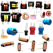
INDUCTORS:
Inductance is a property that opposes current flow. Current through an inductance can not change instantaneously. The voltage across a pure inductor leads the current through it by 90 degrees. Different types of materials are used for making coils and transformers. These includes iron cores, powered iron cores , ferrites etc.
 |
| Inductors |
V=L di/dt
i= 1/L ∫ V dt
v-voltage
i-current
L-inductance


.jpg)
No comments